


Joe Pie has now built all four core RETROL kits on camera: the SE-01 Beam Engine, the SE-02 Horizontal Mill Engine, the SE-03 Boiler Kit, and the GF-01 Mini Workshop. Across those builds, he called out dozens of small tips, warnings, and fixes that never made it into the printed instructions.
We pulled every one of them together into a single reference guide, organized by model and by build step, so you can check a tip before you hit a snag instead of pausing your build to go dig through a video.
Bookmark this page. It's meant to sit open on your bench next to the printed manual.
Before You Start: General Tips That Apply to All Four Kits
- Unpack everything before you start. Joe lays out every bag and subassembly first and checks it against the parts list. It's much easier to spot a missing or extra part before you're mid-build.
- Don't confuse part numbers with screw length. On the SE-03 kit specifically, Joe flags that the cap screw part number is not the same as its length in millimeters — a genuinely easy mix-up to make.
- Use an O-ring on every fitting. Boiler-equipped kits (SE-03, and to a lesser extent SE-01/SE-02) rely on silicone O-rings at nearly every valve, gauge, and bung connection. Take them slow — they're easy to knock out of place while you're aligning a fitting.
- Snug before you torque. On multi-point assemblies (bearing blocks, boiler pillars), Joe consistently assembles everything loose first, lets it "float" into alignment, then tightens everything down as a final pass. Don't fully torque the first screw you install.
SE-01 Beam Engine — Assembly Tips
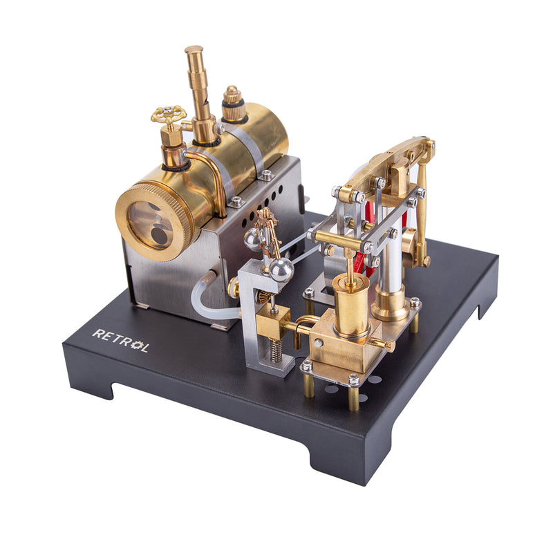
Joe's Verdict: a clean, well-illustrated build, easy enough to finish in under two hours, with only one delicate step worth slowing down for.
Step 3 — Piston stroke must move freely
Before moving on, confirm the piston has full, unobstructed travel: all the way up, and all the way down. If you feel any resistance, the base screws on these components are your adjustment point. Loosen them just enough to shift the parts until the piston moves freely and looks parallel — you're aiming for both fit and cosmetic alignment at the same time.
Step 4 — Clocking the beam arm (the delicate one)
This is the step Joe warns about most directly. The beam arm assembly is genuinely delicate — push too hard while adjusting it and you risk bending or breaking a part.
- The governor post is aluminum. If you drive the set screw down hard, it will dig a small dimple into the post — and the screw will "remember" that spot, making fine side-to-side adjustments difficult afterward
- You're aiming for minimal, almost-absent resistance when you swing the beam arm side to side
- If you've already locked it down too tight, don't force it. Loosen the base screw and rotate the entire post to find your angle, rather than fighting the set screw
- The smoother this assembly moves by hand now, the smoother the finished engine will run
A manufacturing burr to check for
Joe encountered a small burr on either side of an undercut on one rod, which caused it to hang up instead of passing cleanly through its mounting block. If yours does the same: pull the rod back out and lightly stone or file the undercut edges until it's burr-free, then reinstall.
The flyball governor, once it's together
Once the linkage connects to the governor, you'll see the mechanical action that gave machinists the phrase "balls out" — as RPM increases, the weights swing outward from centrifugal force and lift the steam valve, regulating speed. It's worth pausing to actually watch this happen before you close the model up.
Shop RETROL SE-01 Beam Steam Engine
SE-02 Horizontal Mill Engine — Assembly Tips
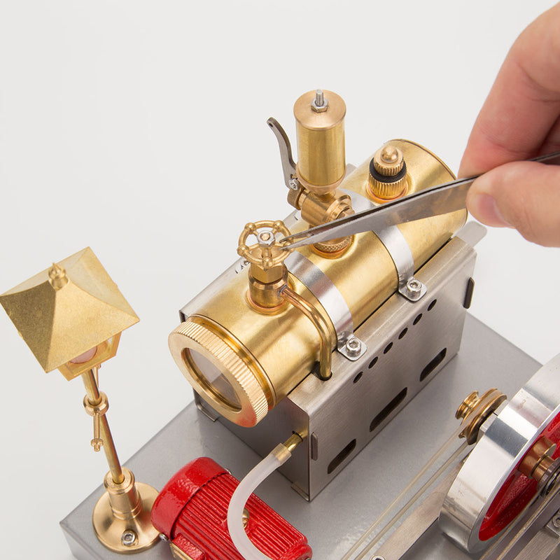
Joe's Verdict: superb fit and finish, but this is the kit most likely to give you a hard bind on first assembly. It's a known, fixable issue — not a defect.
The flywheel bind (the #1 issue builders hit)
As you rotate the flywheel through a full turn for the first time, the linkage on the reverse mechanism can bind solidly against the valve compression. Joe called this "a very solid bind" in his own build. Here's the fix:
- Locate the four screws holding the standoff block in place, underneath the mechanism
- Loosen all four screws to relieve tension on the block
- Shift the block as far outboard (outward) as it will go
- Make sure the installation gap between the shaft and its collar/cam is snug — not loose, not overly tight
- Re-tighten the four standoff screws once the bind clears
Joe's Pro Tip: do not try to force the engine to run through a bind like this. It's completely free once the standoff block is repositioned — forcing it risks damaging the linkage.
Running on air instead of steam
If you want a clean, fuel-free display, both the SE-01 and SE-02 can run on compressed air. Simply disconnect the steam chest and feed air through the port instead. This is exactly how Joe demos the SE-02 on camera without ever putting water or fuel in the boiler.
What makes the SE-02 different from the SE-01
Where the SE-01 is a beam-engine layout, the SE-02 is a horizontal single-cylinder design with a genuine reverse mechanism — a smaller manifold, more compact construction, and (per Joe) a mechanism he hadn't personally seen in this style before. It's 39 unique parts, roughly 100 pieces total, and 19 steps — slightly more involved than the SE-01's 16-step sequence.
Shop RETROL SE-02 Horizontal Mill Steam Engine
SE-03 Boiler Kit — Assembly Tips
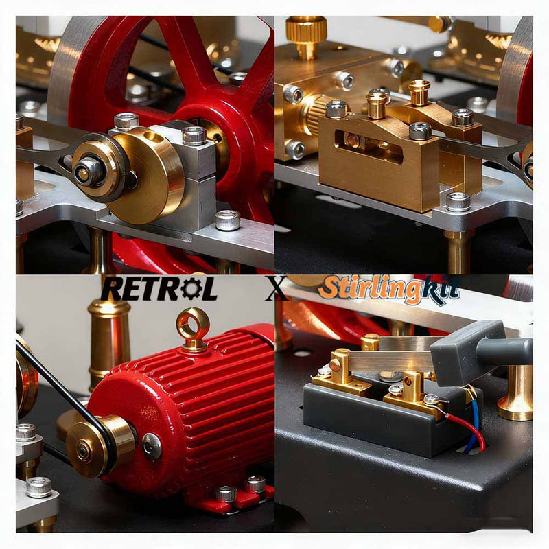
Joe's Verdict: the most mechanically involved build of the four, and the one with the most individual tips worth tracking. Nothing here is difficult — it's just a longer list of "do this before that."
Bearing blocks: let them float first
When installing the six screws on the two sizes of bearing blocks, don't fully tighten them right away. Leave them loose enough to shift position, install the main base plate, and only tighten everything down once it's all aligned. Joe installs standoff pillars diagonally opposed first (roughly ten around the perimeter), snugs them lightly to hold position, then torques everything down as a final pass — larger side of each pillar goes down.
Flywheel shaft choke collar orientation
The choke collar has a small counterbore on the same side as the cap screw heads. It might look like the O-ring groove should sit inside that counterbore — but that's not how the instructions actually show it. Double-check the illustration before you commit, since it's easy to assemble backward from what looks intuitive.
Critical: install this eccentric before the flywheel
This is the single most important sequencing tip from the whole SE-03 build, and it's genuinely missing from the printed manual. The eccentric that controls the crosshead — along with the O-ring that connects to the flyball governor — needs to go on before you install the flywheel and seat the bearings on the bearing blocks. Miss this step order and you'll have to partially disassemble what you just built.
- Make sure the eccentric lines up with the flats on the flywheel shaft before seating
- Don't connect the governor O-ring yet at this stage — wait until the shaft isn't under load, to avoid putting undue pressure on it
Setting a grub screw on a flat shaft (technique that works every time)
Run the set screw down until you feel gentle pressure, then oscillate the wheel/shaft back and forth until you feel it drop into resistance — that's how you know you've found the flat. Only then drive the screw fully down. Joe uses this same technique throughout the build wherever a set screw needs to land on a shaft flat.
Don't mix up the O-rings
Several O-rings in this kit look nearly identical side by side but are actually different sizes for different locations. If you swap two by mistake, the model will usually still go together and even function — but one fitting will end up tight and another loose. Take a moment to sort and identify them before installing.
Wiring and lamp installation
- Generator wires route straight down through the base — not through the channel on the post, which is a natural but incorrect guess
- Twist the lamp's wire ends together before feeding them down through the standoff — it self-guides much more easily and avoids catching on the base
- Right side of the terminal block connects to the generator, left side to the lamp; red to red, black to black throughout
The pressure control valve fitting you should remove
On the third bung around the boiler (the pressure control valve), there's a small piece that appears designed to screw in before the cap — but doing so makes the fitting impossible to seat correctly. Joe found that this piece needs to be removed entirely before installing the O-ring and tightening the valve down. It may be intended for a different variant of the kit.
Testing the light without steam
With the switch in the closed position, pull down on the flywheel by hand — the light should strobe on and off as it spins. This is a fast way to confirm your wiring and generator connections before you ever fire the boiler.
Shop RETROL SE-03 Boiler Steam Engine
GF-01 Mini Workshop — Assembly Tips
Joe's Verdict: a straightforward build on its own, with two sequencing tips that save you real hassle later, plus the payoff of connecting it to the SE-03.
Install the battery holder before the top components
The battery holder ends up underneath components on the top of the model. If you install it after everything else is assembled, you'll have to lay the finished model on its side and put pressure on the top-mounted parts to get access. Locate and install the battery holder early, before you build up anything on top of the base.
Belt and pulley alignment
- There are no flats on this shaft to help you align the pulleys — you have to eyeball it against the belts
- Don't fully tighten the set screw until you've confirmed the belts are parallel to each other and perpendicular to the shaft and pulleys
- Go easy on initial torque so you don't mar the shaft, then add more pressure once you're confident the alignment is correct
An optional step worth doing anyway
The instructions don't call for it, but Joe recommends installing the grub screws in all the pulleys as you go, simply because it's easier to keep track of small parts once they're installed rather than set aside.
Displaying it statically? Leave the belts off
If you're planning to keep the GF-01 as a static display piece rather than driving it, don't install the three included drive belts. Leave them off and tape them to the underside of the display base instead. That way the model looks intentional rather than "broken," and you can add the drivetrain later without disassembling anything.
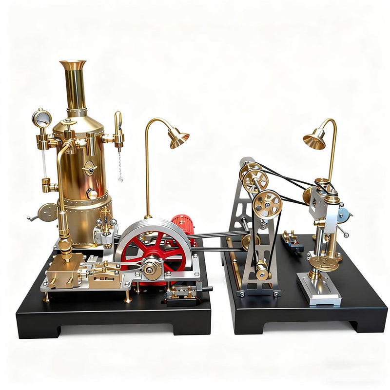
Connecting it to the SE-03
The GF-01's three-wheel pulley is specifically positioned to line up with an extra pulley position on the SE-03's flywheel. With the drive belts connected, one steam engine powers the drill press, the pedestal grinder, and lights the streetlamp, all at once. If you're building both kits, this is worth planning for from the start rather than as an afterthought.
Shop RETROL GF-01 Mini Workshop
Quick Reference: Symptom → Fix
| Model | Symptom | Fix |
|---|---|---|
| SE-01 | Beam arm sticky or hard to adjust side to side | Loosen the base screw, rotate the whole post rather than forcing the set screw |
| SE-01 | Rod won't pass fully through mounting block | Check for a manufacturing burr on the undercut; stone or file it smooth |
| SE-02 | Flywheel binds solidly partway through rotation | Loosen the 4 standoff screws, shift the block outboard, re-tighten |
| SE-03 | Can't seat bearings correctly / eccentric out of position | Install the crosshead eccentric and governor O-ring before mounting the flywheel |
| SE-03 | Pressure control valve won't seat | Remove the extra fitting piece before installing the O-ring and valve |
| GF-01 | Hard to access battery holder after assembly | Install the battery holder before adding top-mounted components |
| All boiler kits | Fitting feels loose or too tight | Check you haven't swapped two similar-looking O-rings between locations |
That's every build tip Joe Pie has shared across all four RETROL kits so far. If you're working through a build right now and hit something not covered here, the full videos are linked in each section above — Joe walks through every one of these fixes live on camera.


0 comentarios