

How to Adjust a Torque Screwdriver for Model Engine Kits
Small threads strip easily. Here's how to control your fastening force — and which positions actually need it.
A torque screwdriver is one of those tools that looks simple until you try to use it for the first time and nothing happens. The adjustment ring won't move. The clutch won't click. Two screwdrivers, same problem — so is the tool broken, or is there a step being skipped?
Usually, there's a step being skipped. Most adjustable torque screwdrivers have a locking mechanism on the handle that must be disengaged before the torque setting can be changed. This guide covers that unlock procedure, explains why torque control matters specifically for miniature metal engines, and gives you a reference table for the fasteners you'll encounter in assembly.
Why torque control matters for miniature engines
Real engines use steel fasteners threading into cast iron or aluminum. Miniature model engines are similar — but at a fraction of the scale. An M2 screw has a thread diameter of 2 mm. Stripped threads at this size cannot be re-tapped without special equipment, and in many cases the component is ruined.
The two failure modes are opposite but equally damaging:
Over-tightened: Thread stripping in aluminum housings, cracked cylinder head covers, or distorted sealing surfaces. These are assembly errors that cannot be undone.
A torque screwdriver eliminates the guesswork by slipping or clicking when a preset force is reached, preventing you from applying more torque than the fastener can handle.
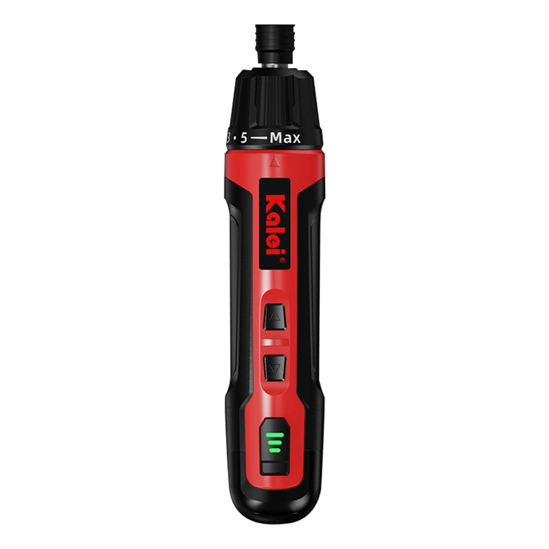
Step 1 — Unlock the torque setting before adjusting
This is the step most first-time users miss. On virtually all adjustable torque screwdrivers, the torque value is set by rotating the handle — but the handle is locked by default to prevent accidental changes during use.
- Hold the screwdriver with the tip pointing away from you. Look at the base of the handle — you'll see a locking collar or ring, usually with a knurled texture or a marked LOCK/UNLOCK position.
- Rotate this collar in the UNLOCK direction (typically counterclockwise, or toward the unlock symbol). Some models require pressing down while turning.
- Once unlocked, rotate the handle itself to change the torque value. Counterclockwise lowers the setting; clockwise raises it. The scale on the handle indicates the current value in N·cm.
- When your target value is set, rotate the locking collar back to LOCK before using the screwdriver. This prevents the value from drifting during tightening.
Step 2 — Understand how the clutch works
Torque screwdrivers work differently from regular screwdrivers. When the preset torque is reached, the internal mechanism slips or clicks — you'll feel it clearly in your hand. This is normal and intentional. Stop driving the fastener the moment you feel or hear the slip.
Common mistakes after the click:
Continuing to turn after the slip
The clutch disengaging does not mean the screw is locked — it means the limit has been reached. Continuing to turn applies force through mechanical friction and can still strip the thread. Stop immediately when the clutch releases.
Setting the torque too high "just to be safe"
Higher torque does not mean more secure. Each screw size and material combination has a recommended range — exceeding it damages the fastener or the receiving thread. Use the reference table below as a starting point.
Torque reference table for model engine fasteners
These are working ranges for common fastener types found in miniature 4-stroke gasoline engine kits. Always defer to the specific torque values in your engine's assembly manual if provided. When in doubt, start at the lower end of the range.
| Fastener | Location (typical) | Material | Torque Range | Notes |
|---|---|---|---|---|
| M2 × 0.4 | Valve cover, small brackets | Steel into aluminum | 3 – 5 N·cm | Snug only — these strip easily |
| M2.5 × 0.45 | Carburetor mount, ignition bracket | Steel into aluminum | 5 – 8 N·cm | Check for thread engagement depth |
| M3 × 0.5 | Cylinder head bolts, crankcase | Steel into aluminum | 10 – 15 N·cm ★ | Critical — tighten in cross pattern |
| M3 × 0.5 | Cylinder head bolts, crankcase | Steel into steel | 15 – 20 N·cm | Refer to manual for sequence |
| 1/4-32 (Imperial) | Spark plugs | Steel into aluminum head | 8 – 12 N·cm ★ | Use dedicated spark plug socket tool |
| M4 × 0.7 | Engine mount bolts, base plate | Steel into steel | 25 – 35 N·cm | Less critical — inspect for strip |
★ These positions are the highest risk for damage if over-tightened. Always tighten in stages — reach 50% of the target value first on all fasteners, then return to full torque.
Position-by-position guide: where torque control matters most
Cylinder head bolts
The highest-priority position in the entire build. Head bolts must be tightened in a cross (star) pattern, not in a circle. Tighten in two passes: first to half torque, then to full torque. Uneven tightening distorts the head gasket surface and causes compression loss or leaks after the first run.
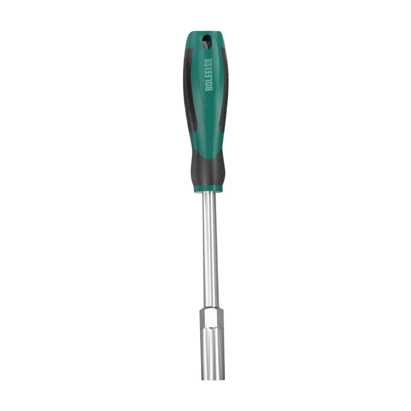
Spark plugs
Most miniature engines use an imperial thread — 1/4-32 for many CISON and TOYAN variants. The aluminum thread in the cylinder head is soft. Finger-tight plus a quarter turn is typically sufficient for a new plug with a crush washer. Use a dedicated hex socket spark plug tool rather than a flat-grip screwdriver for better feel and access. The 6mm Hex Socket Spark Plug Tool is purpose-built for this thread size.
Carburetor mounting screws
These fasten the carburetor body to an aluminum intake manifold. The threads are short and the material is soft — easy to strip with a standard screwdriver if you're working quickly. M2.5 is common here; keep torque in the 5–8 N·cm range.
Crankcase and main bearing bolts
These hold the two halves of the engine block together. Overtightening can distort the bearing bore and increase internal friction. Follow the assembly manual sequence strictly if one is specified.
Valve cover screws
Cosmetic and light-sealing function — these are some of the smallest screws on the engine. Snug only. If you're using a standard screwdriver here, keep grip force deliberately light.
When you do not need a torque screwdriver
Not every fastener on a model engine requires precise torque control. Non-critical positions — stand brackets, display base mounts, decorative panels — can be tightened with a standard precision screwdriver. The goal of torque control is to protect structural and sealing joints, not to process every screw on the engine equally.
A good mental model: if a screw is sealing something (combustion chamber, oil gallery, intake tract) or holding something that must not move under vibration (head, crankcase, spark plug), use torque control. If it's a cosmetic or structural-only screw on a non-vibrating component, standard tightening is fine.
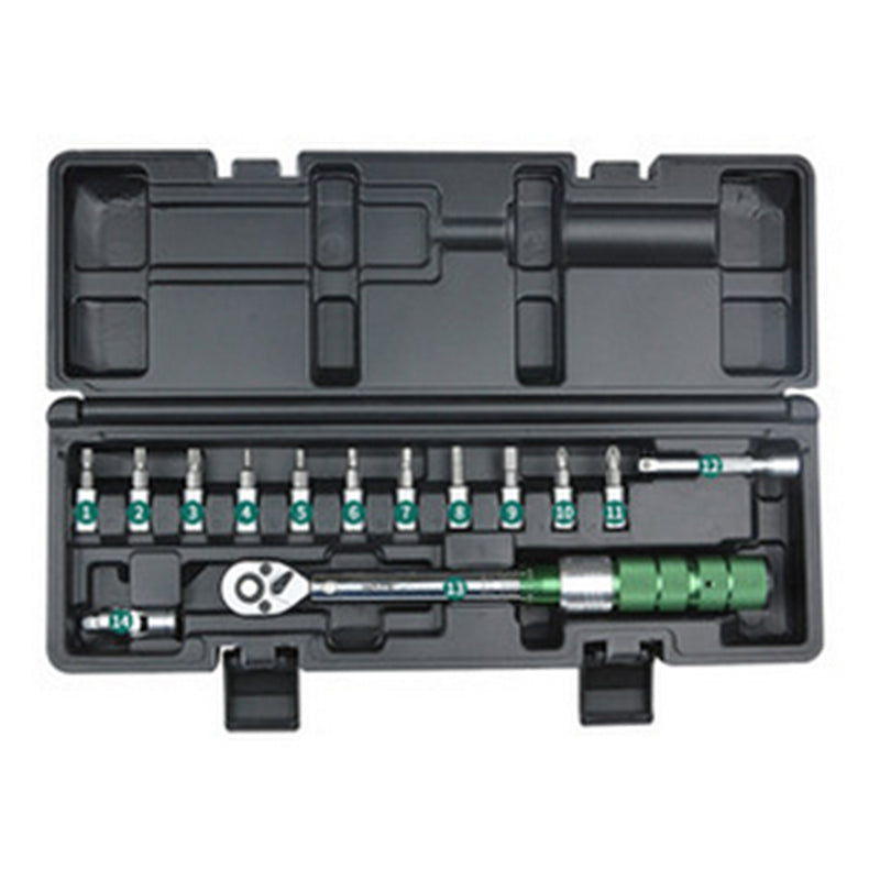
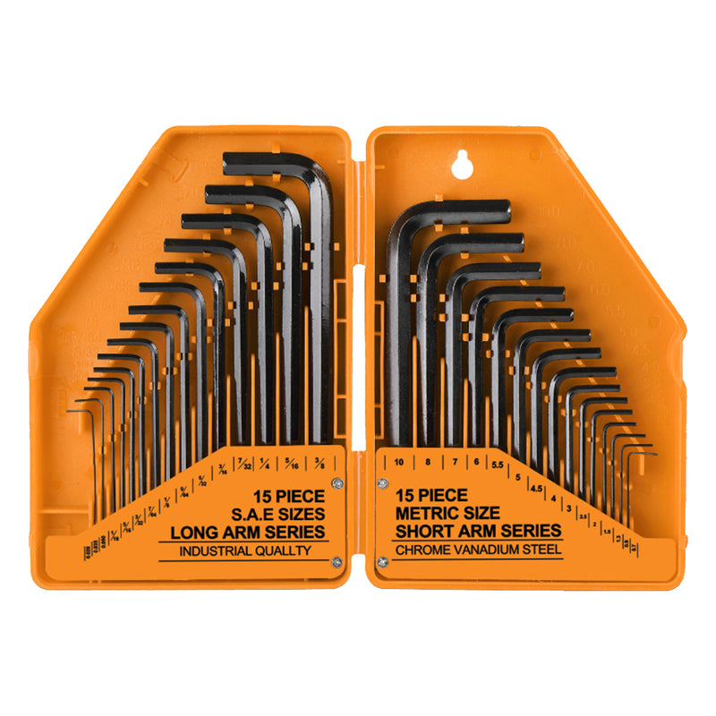
Recommended tools for model engine assembly
The tools below are stocked by Stirlingkit and are suited to the fastener types found in miniature 4-stroke engine kits.


Common questions
My torque screwdriver handle won't rotate even after unlocking the collar — what's wrong?
I ordered two torque screwdrivers and both have the same problem. Does that mean it's a manufacturing defect?
Does every screw on my engine kit need a specific torque value?
The assembly manual doesn't specify torque values. What should I use?
Can I use the torque screwdriver for spark plug installation?
Was this guide helpful?
Take a 1-minute survey and help us make our tutorials better.
Browse the full tool range
Screwdriver sets, hex keys, spark plug sockets, and everything else you need to build cleanly.
Shop Engine Tools


0 commenti